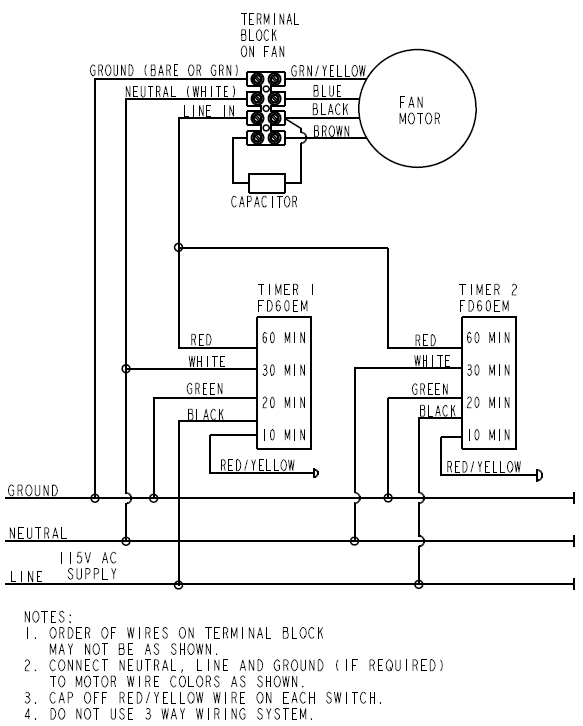
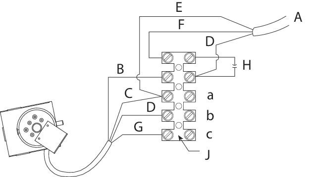
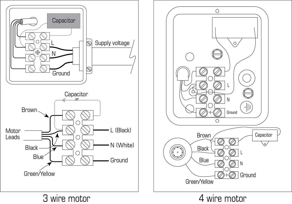
Fantech Radon Fan Wiring Diagram

With a record low power consumption of 20 w this radon fan is the perfect choice where there is good sub slab communication and lower radon levels.
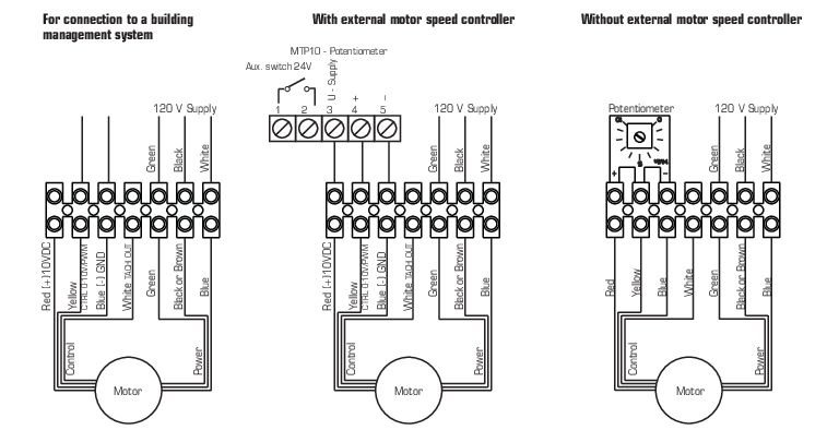
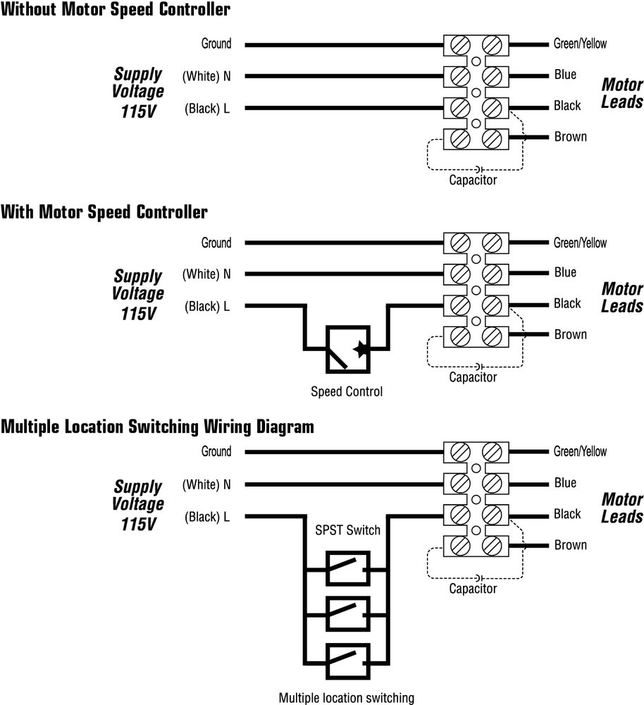
Fantech radon fan wiring diagram. Such systems are designed to remove radon gas before it migrates to a building s interior. We are committed to making products that support healthy and comfortable indoor environments and ensure your loved ones breathe fresh clean air from this moment to the next. These systems are designed to remove radon gas before it migrates into the building envelope. The fan can be mounted both indoor outdoor and in wet locations.
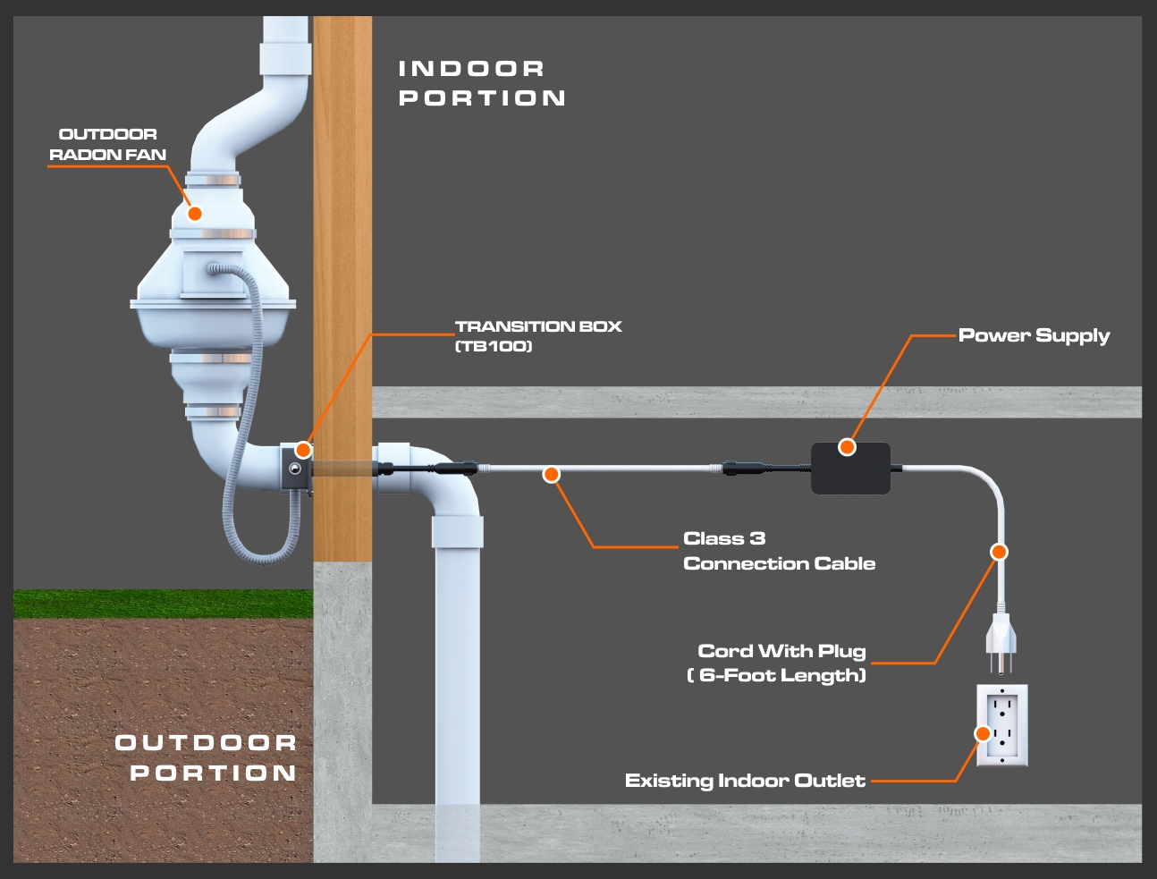
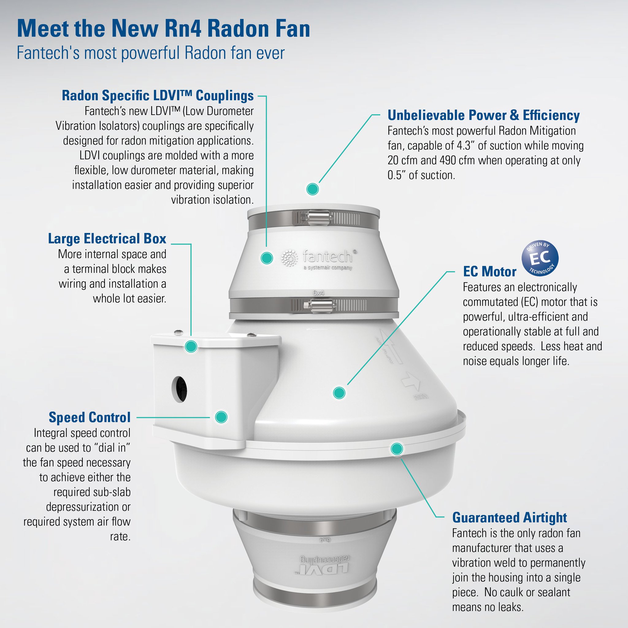
970 599 1872 there are electrical code requirements. Radon mitigation fans active radon mitigation systems employ specialized fans to exhaust radon gas from underneath building structures via a sealed pipe system. As the most powerful model in fantech s family of radon mitigation fans the rn 4ec can create 4 3 of suction while moving 20 cfm as well as move 490 cfm when operating at only 0 5 of suction. The fan features a fully sealed plastic housing.
Fantech does much more than make fans. Collection of fantech wiring diagram. High air flow high suction. Fans for bathroom exhaust dryer ehxaust radon mitigation inline supply and exhaust air fans makeup air systems.
To simplify installation use frik 4x3 or frik 4x4 installation kits. Performance certified by hv i. A large electrical wiring enclosure is designed into the fan housing making electrical installation easier. Safety certified by ul.
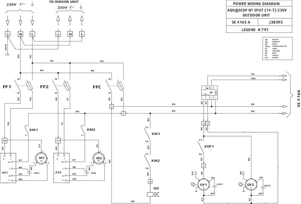
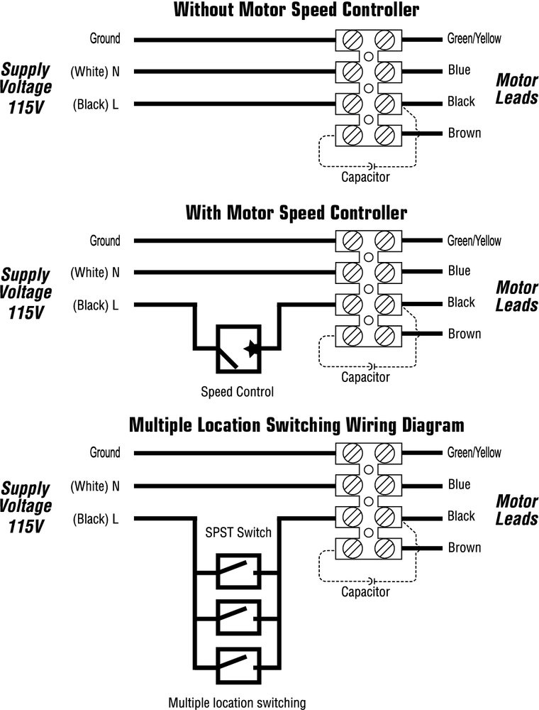
Installation instructions is part of fantech s technical library that is designed to give fantech customers appropriate information about installation instructions adjustable pitch axial flow fans motor types and specifications noise acoustic installation maintenance instructions and installation guide on what to do s and don ts. 3ø wiring diagrams 1ø wiring diagrams diagram er9 m 3 1 5 9 3 7 11 low speed high speed u1 v1 w1 w2 u2 v2 tk tk thermal overloads two speed star delta motor switch m 3 0 10v 20v 415v ac 4 20ma outp uts diagram ic2 m 1 240v ac 0 10v outp ut diagram ic3 m 1 0 10v 4 20ma 240v ac outp uts these diagrams are current at the time of publication. Click on the image to enlarge and then save it to your computer by right clicking on the image. Because at fantech we re not just building fans we re building solutions and opportunities for a healthier safer tomorrow.
Fantech wiring diagram fantech fan wiring wire center u2022 rh silaiwala co fantech dryer booster fan fantech fans 4. The inlet and outlet pieces of the housing are joined via a vibration welding process.


